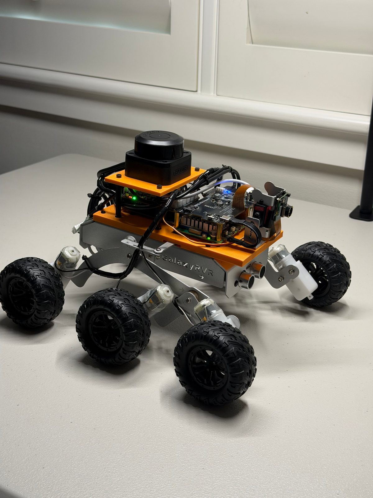
- Drive
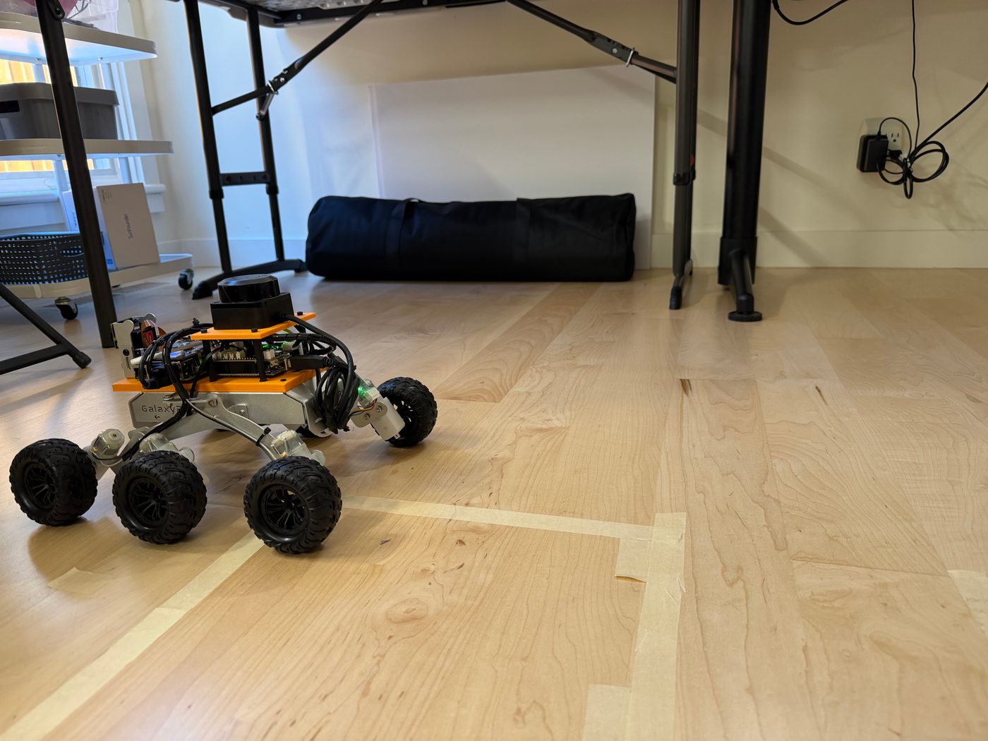
- 6 wheelsskid steer, TT motors
- Computer
- Pi 5, 8 GBown battery
- Lidar plane
- 183 mmabove the floor
- First go-to
- 3 of 3within 100 mm, by tape
- Parts cost
- ≈ $280new parts; see list
3D model
The two orange parts are the printed plates, the same files you can download. The translucent blocks are simplified envelopes of the boards, the lidar and the standoffs, placed from the build's measurements.
Drag to turn, scroll or pinch to zoom, right-drag to pan.
Parts list
Prices are what we paid, where we recorded them. Parts we already owned have no price.
| Part | Role | Qty | Paid |
|---|---|---|---|
| Base | |||
| SunFounder GalaxyRVR kit | Chassis, six TT motors, Arduino-compatible R3 board, GalaxyRVR shield, battery. Solar panel left off. | 1 | ≈ $130 |
| Computer and power | |||
| Raspberry Pi 5, 8 GB | Records camera and lidar, relays drive commands | 1 | owned |
| Pi case base with active cooler | Cooling under load | 1 | owned |
| microSD card, 128 GB, A2 | Boot and storage. Our first card failed; see lessons. | 1 | owned |
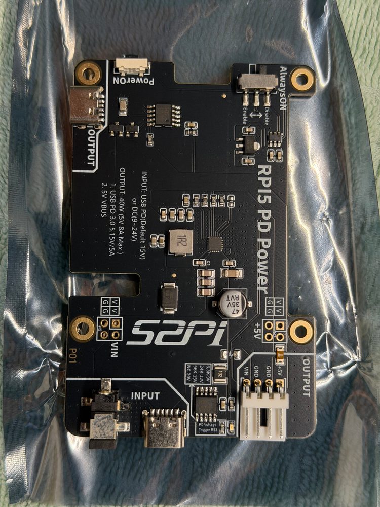
| 52Pi EP-0225 USB-C PD board | Takes 15 V USB-C PD, gives the Pi a regulated 5 V | 1 | $29.99 |
| Anker MagGo A1664 power bank | The Pi's own battery, 39 Wh | 1 | owned |
| Sensors | |||
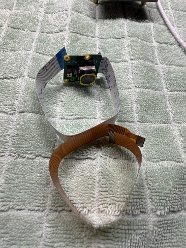
| Arducam B031202, 12 MP IMX708 | Front camera, 120° diagonal, autofocus | 1 | $44.99 |
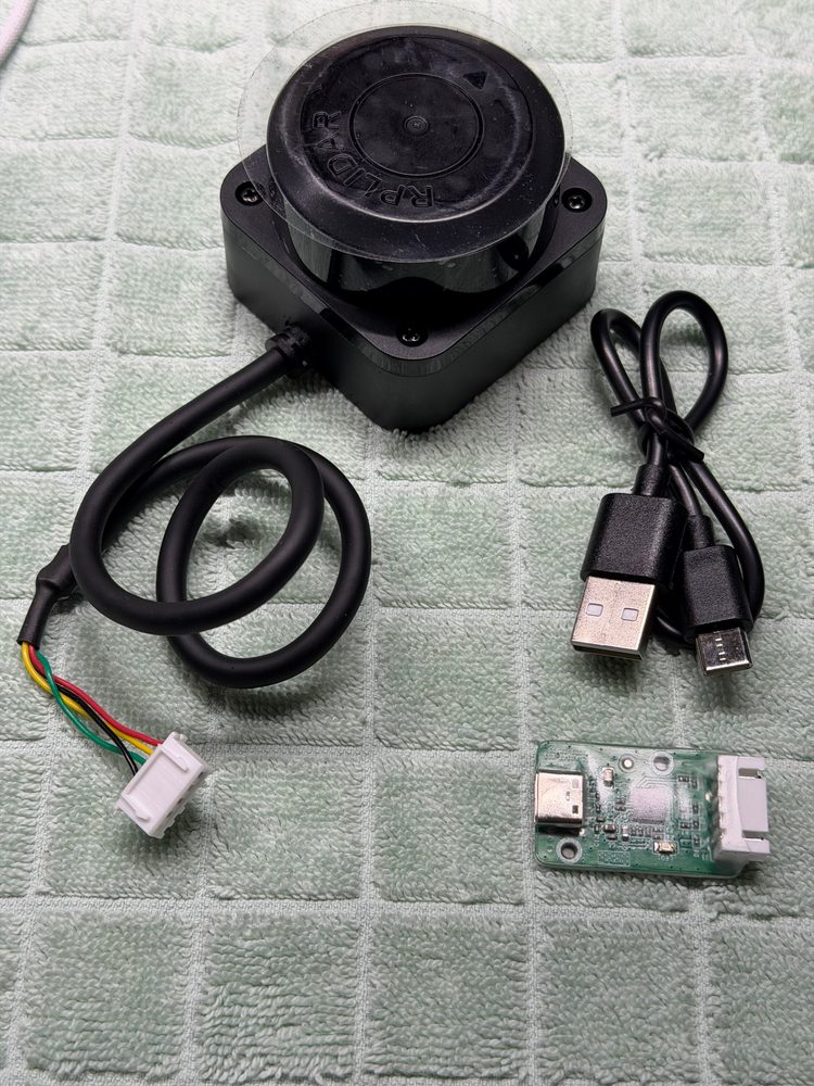
| SLAMTEC RPLIDAR C1 kit | 360° single-plane lidar, with its USB adapter | 1 | $74.99 |
| Printed and hardware | |||
| Lower plate, PLA | Payload deck on the chassis | 1 | printed |
| Lidar carrier, PLA | Raised lidar deck | 1 | printed |
| M3 metal standoffs, 45 mm stack | Lidar carrier supports | 4 | owned |
| M3 flat-head socket screws and nuts | Camera bracket (2) and standoff bases (4), up from below | 6 | owned |
| M3 screws and hex nuts | Controller board into captive nuts under the plate | 4 | owned |
| M3 screws | Plate to chassis (4), carrier to standoffs (4) | 8 | owned |
| M2.5 button-head socket screws | Pi, up through the plate into the EP-0225 standoffs | 4 | owned |
| M2.5 screws | Lidar to carrier, from below, at most 4 mm into the lidar | 4 | owned |
| Cables and control | |||
| USB-A to USB-B cable, 5 V wire cut | Pi to controller board: data and ground only | 1 | owned |
| PS4 DualShock 4 controller | Plugged into the laptop for driving | 1 | owned |
| New parts bought for this build | ≈ $280 | ||
Screw lengths were not recorded; measure against your own stack. The kit's ESP32 camera is disconnected from the shield.
Two batteries, kept apart
Printed parts
Both parts were printed in PLA on a Bambu Lab A1 mini. The lower plate takes the solar panel's place and bolts into the chassis's existing threaded holes. A 21 mm channel under the plate clears the chassis strip and keeps the top flat.
| Material | PLA |
|---|---|
| Walls, infill | 4 wall loops, 15 % gyroid |
| Around holes | Slicer modifiers at every through-hole |
| Orientation | Lower plate top face down, so the nut pockets and channel print facing up. Carrier flat. |
| Fasteners | No heat-set inserts: captive M3 nuts, countersunk screws from below, and the EP-0225's own standoffs |
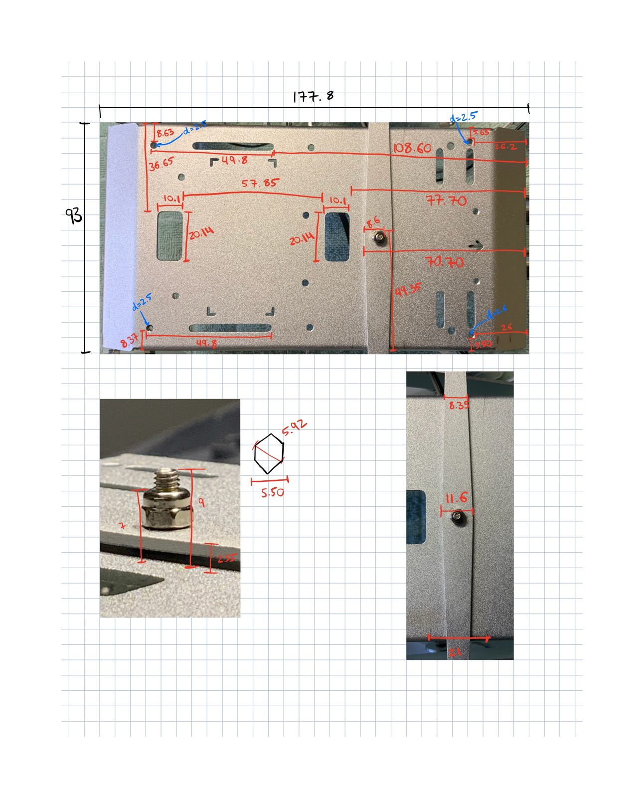
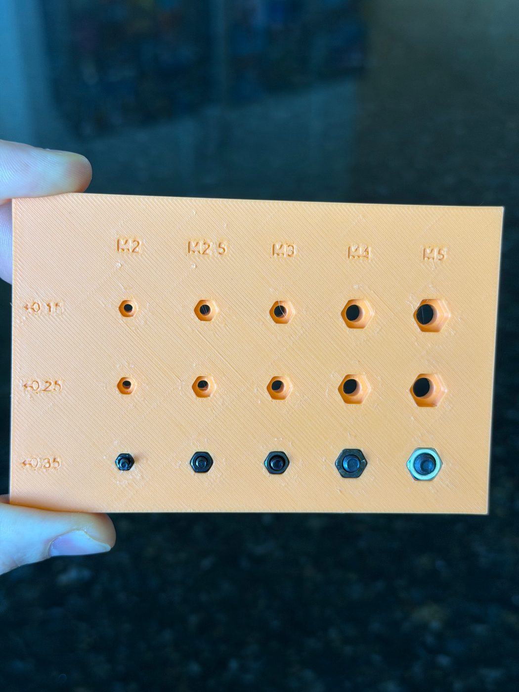
The files here are rebuilt from the build's measured specification by cad/build_parts.py (FreeCAD). They include one change made after printing: the camera bracket holes sit 5 mm farther along the plate's width, where we re-drilled them to clear the Pi's power cable. Two walls are thinner than our own 2.5 and 3 mm minimums: between two nut pockets and the channel (1.1 mm), and the roof over two Pi screw pockets inside the channel (2.6 mm).
Assembly
- Build the kit with SunFounder's assembly video, but leave off the solar panel and its mount. Its space becomes the payload deck.
- Print the lower plate and the lidar carrier.
- Press four M3 nuts into the hex pockets under the plate, for the controller board.
- Fit the camera bracket and the four standoff bases with M3 countersunk screws pointing up from under the plate, nuts on top. Build each standoff stack to 45 mm.
- Mount the Pi with the EP-0225 on it: four M2.5 button heads up through the plate into the EP-0225's standoffs. Do this before the plate goes on the chassis, which covers those screw heads.
- Mount the R3 board and shield under where the lidar will be, with M3 screws from the top into the captive nuts.
- Bolt the plate to the chassis with four M3 screws into the chassis threads. The channel underneath sits over the chassis strip, and the 8 mm hole clears its center screw.
- Fit the lidar to the carrier with four M2.5 screws from below, then screw the carrier onto the standoffs from above.
- Connect the camera to the Pi's CAM/DISP 0 port with a 22-pin Pi 5 ribbon. Never plug it into the kit's ESP32 camera connector: it looks similar and is not compatible.
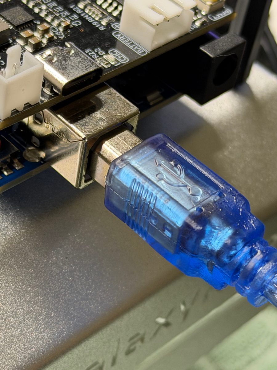
- Wire it up: lidar USB adapter to a Pi USB 2 port, wrapped in film and taped where it touches the chassis; R3 to the Pi with the modified cable; power bank to the EP-0225's USB-C input.
- Before every drive: both batteries strapped down, loose cable coiled away from the wheels and suspension, and nothing in the lidar's scan plane.
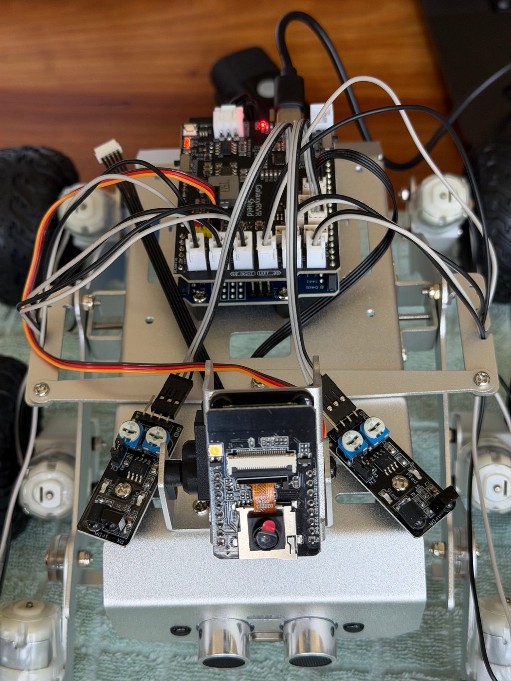
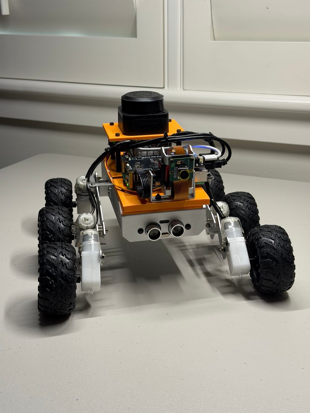
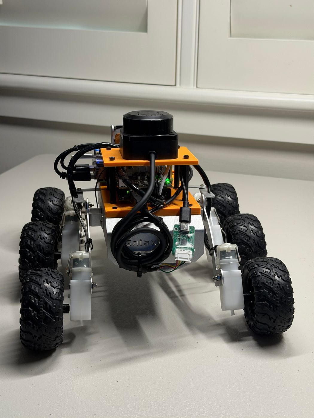
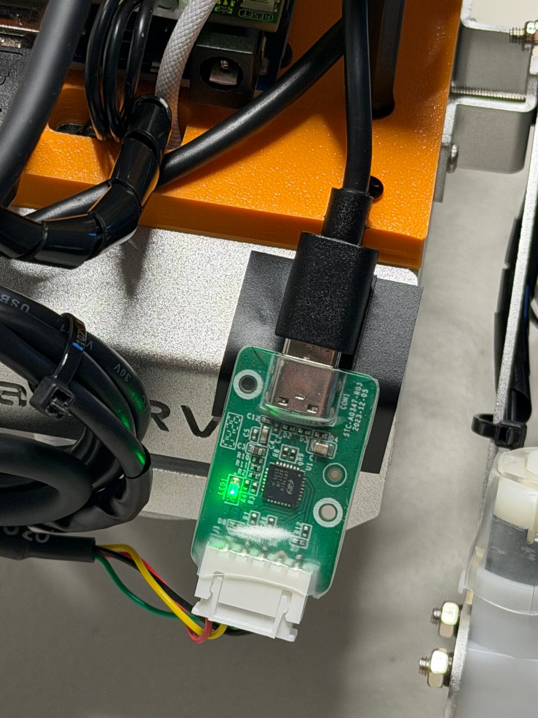
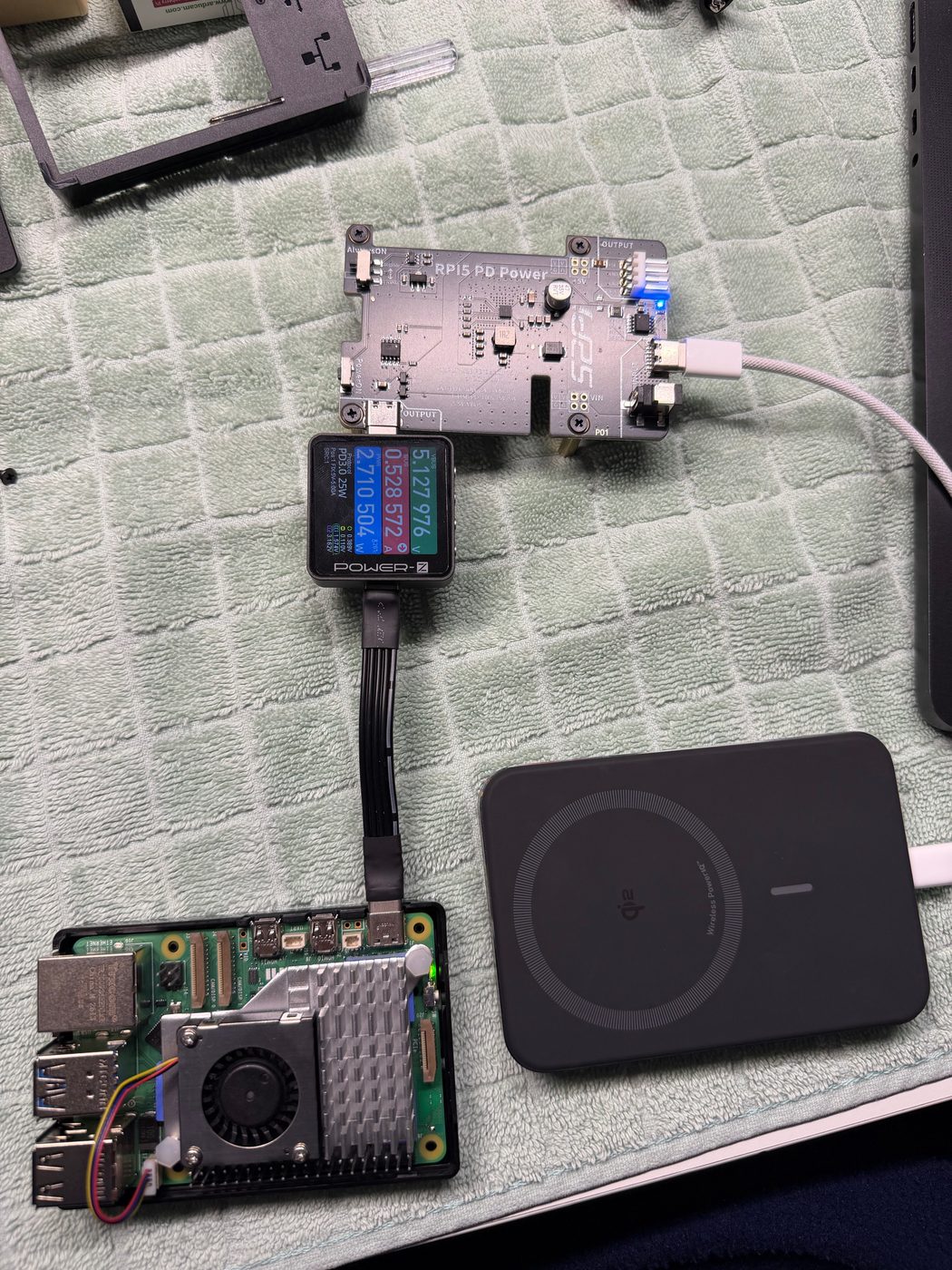
The main parts before mounting
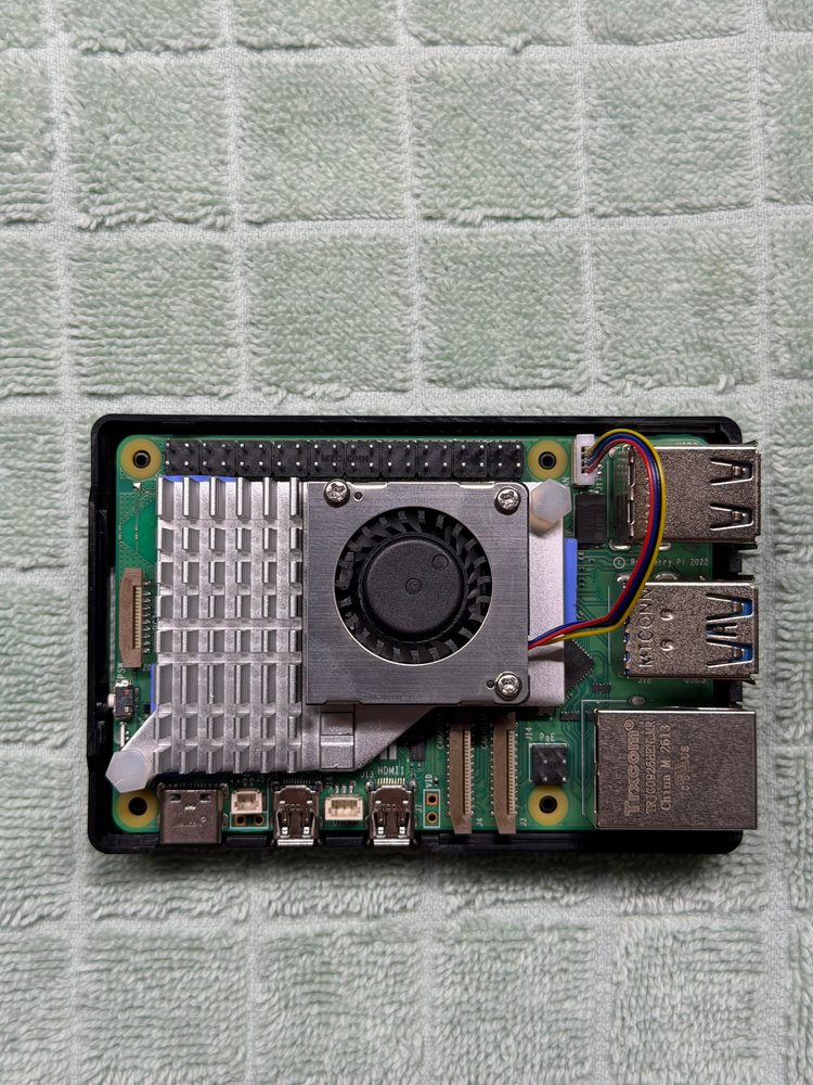
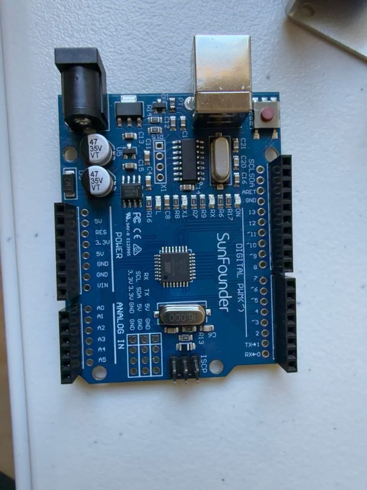
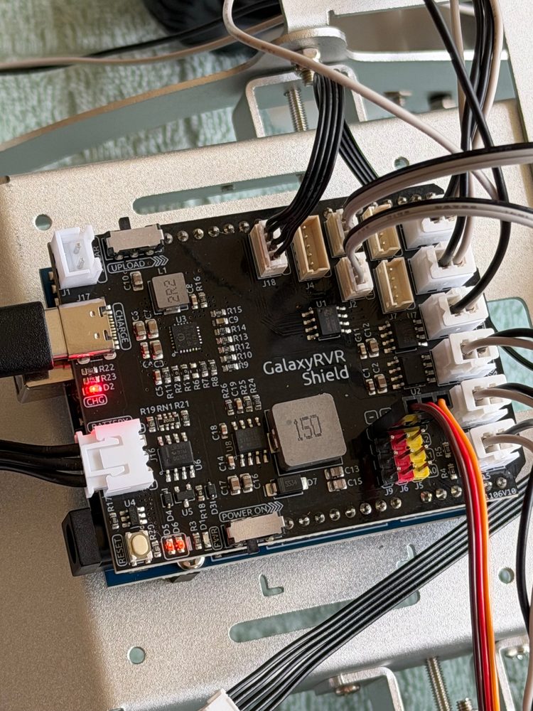
The USB cable we cut
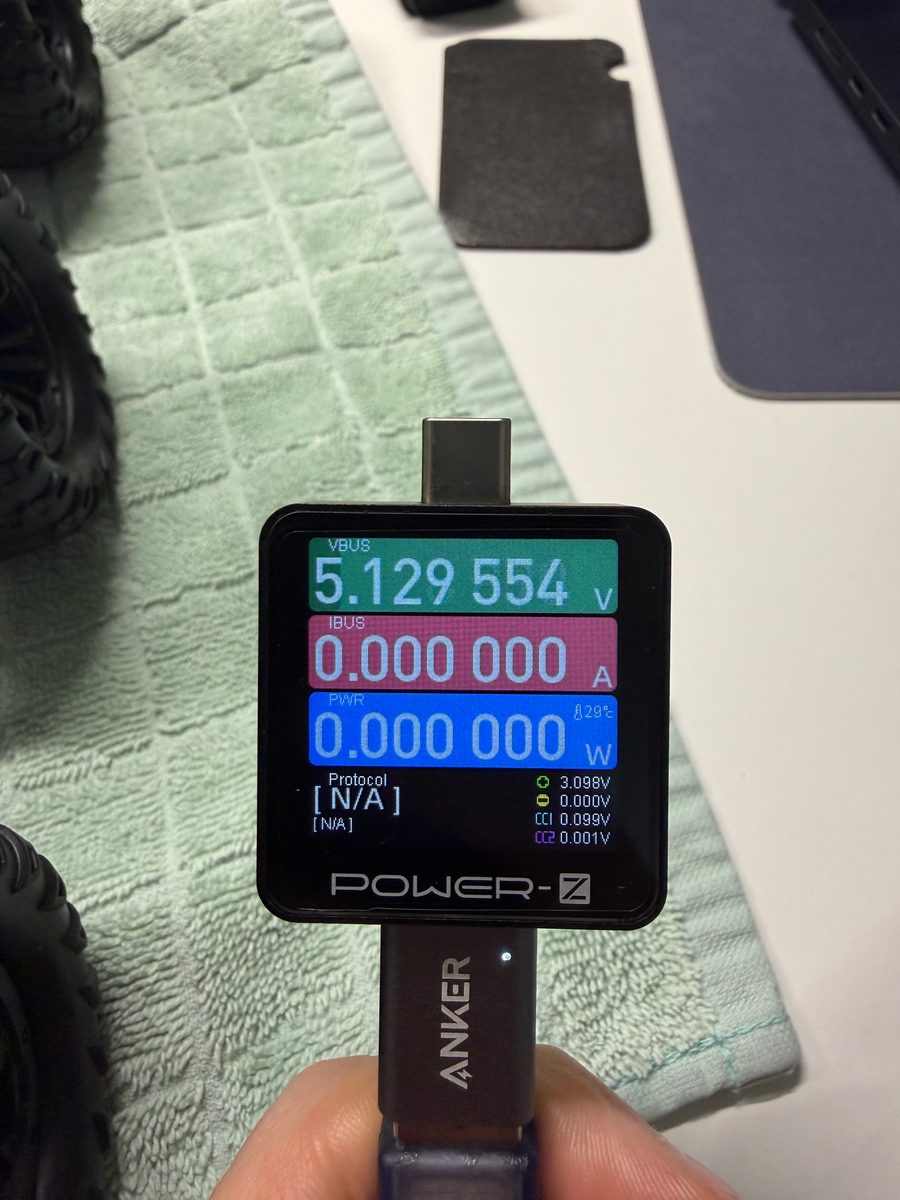
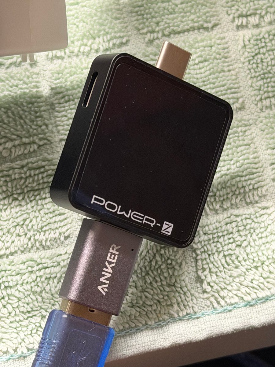
The Pi sends drive commands to the R3 board over USB. But the R3's USB port is also powered by the rover's battery, through the shield. With the rover switched on and nothing else connected, a USB meter on the R3's cable read 5.13 V. Plugged into the Pi, that cable would have tied the rover's 5 V to the Pi's own supply, and current could flow back into the Pi.
So on a spare USB-A to USB-B cable we opened the jacket and cut the red wire, the 5 V line (VBUS). Both cut ends were insulated and the section taped closed. White (D−), green (D+) and black (ground) stay connected: the two boards share data and ground, never power.
How we checked it
Voltage with a POWER-Z KM003C USB meter; the wires with a multimeter in continuity (beep) mode, cable unplugged at both ends.
| Check | How | Result |
|---|---|---|
| Back-feed, stock cable | Rover on, R3 → cable → meter, other end free | 5.13 V |
| Back-feed, cut cable | Same setup with the modified cable | Meter stays dark |
| 5 V end to end | A pin 1 → B pin 1 | Open |
| Ground | A pin 4 → B pin 4 | Beeps |
| Data | A pin 2 → B pin 2 (D−), A pin 3 → B pin 3 (D+) | Both beep |
| No short | 5 V to ground, at each plug | Open |
| Talks to a laptop | Laptop → cable → R3 running a test firmware with the motors disabled | 4 of 4 replies correct |
| Talks to the Pi | Pi → cable → R3, wheels off the ground | One 200 ms pulse, then stopped by itself |
Software
Plain Python, no ROS. Three computers, each with one job:
- R3 board: small custom firmware. It moves only after an ARM command, and a drive command lapses unless the next one arrives in time; a watchdog stops the motors if the link goes quiet.
- Raspberry Pi: records the camera and lidar, and passes drive commands to the R3 only while its own health checks pass.
- Laptop: the operator's page and PS4 controller, and the navigation: a lidar map built from a driven recording, a particle filter to find the rover on it, and A* to plan a path.
The code is not in this repository yet.
Lidar map and the first go-to runs
The lidar sees one horizontal slice of the room, 183 mm above the floor. We drove around the test room for a few minutes, stitched the scans together (scan matching with loop closure) and got this map at 25 mm per cell. The rover then located itself on it with a particle filter and drove to three goals on its own, September 18, 2026.
| Run | Goal distance | Time | Stopped from goal, by tape |
|---|
Depth coverage in 3D
The camera fills in what the lidar's single plane misses: table legs, boxes and everything between the floor and about 0.8 m. Each camera frame gets a depth estimate from a neural network (Depth Anything V2, Large), scaled to agree with the lidar where its scan line crosses the image and with the floor, then placed along the path the lidar measured. This is 213 frames from a 71-second, 2.5 m drive on September 15, 2026, kept at 2 cm spacing.
Loading 1.7 MB of points…
Log
- Kit built and driven with SunFounder's app.
- Driven from a laptop page with a PS4 controller, through the kit's ESP32 link.
- Pi 5 boots from the power bank through the EP-0225 and holds about 5.05 V through a ten-minute CPU load.
- USB cable modified and checked; the Pi drives the motors through the R3 for the first time, wheels in the air.
- Plates printed and everything mounted and wired.
- Five-minute run driving with camera and lidar recording. The SD card started throwing write errors.
- Camera depth fused with the lidar into a 3D map of the room.
- Camera recalibrated with tilted views of a printed target: the first calibration's focal length was about 5 % too high.
- First drive to a point on the lidar map by itself: three of three goals, 1.3 to 1.7 m away, reached within 100 mm (77, 66 and 53 mm by tape), at 20 % power with a hand on the dead-man key.
- First drives outdoors, over a phone hotspot with a proportional PS4 stick: two sessions, 222 s of driving, no faults.
Lessons
- Measure before you connect two boards. A USB port can be a power source. Five minutes with a meter found the back-feed above.
- The SD card was the weakest part. Continuous camera and lidar recording stalled the first card and then gave write errors. We now record to RAM and copy off at the end, and ordered the official Raspberry Pi card to replace it.
- A single-plane lidar is blind below its plane. At 183 mm it missed a 178 mm cylinder and a chair's star base. We mark those as keep-out zones on the map by hand.
- Without wheel encoders, the motion model is a guess. The rover drove 29 % faster than its model said, and overshot every goal by 51 to 64 mm along its heading.
- Tilt the calibration target. Our first camera calibration used almost straight-on views and came out 5 % off; only a cross-check against the lidar showed it.